Table of Contents
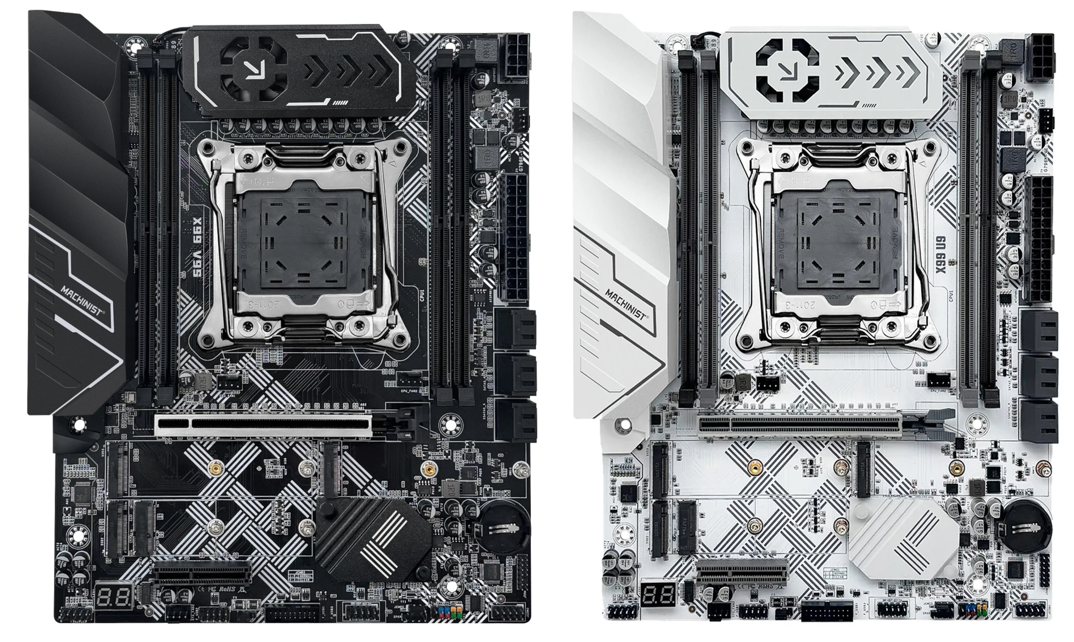
The Machinist X99‑U9 and Machinist X99‑V9s are promising late‑2025 motherboards. The PCBs are labeled G796K‑V.1.0 and, aside from the name, are identical apart from their color schemes.
Unlike many copy‑paste designs out there, these boards were clearly engineered to make far better use of the platform’s capabilities.
Specifications
| Model | Machinist X99-U9 \ X99-V9s |
|---|---|
| Socket | LGA 2011-3 |
| Chipset | C612 |
| Supported Processors | Intel Core i7 (5000, 6000 series, Haswell-E/Broadwell-E) Intel Xeon E5-1600 v3/v4, E5-2600 v3/v4, E5-4600 v3/v4 (Haswell-EP/Broadwell-EP) |
| VRM Configuration | 6 phase Total MOSFETs: 12 (6 high-side + 6 low-side) |
| Supported Memory | 4 x DDR4 DIMM (quad-channel) with ECC and non-ECC support Maximum capacity: 128 GB |
| (S3) Sleep Mode Support | Yes |
| Expansion Slots | 1 x PCI-e x16 (Gen 3.0) 1 x PCI-e x4 (Gen 3.0) |
| Storage | 6 x SATA 3.0 3 x M.2 (NVME, Gen 3.0 x4) |
| Fan Connectors | 1 x CPU cooler (4pin) 3 x Case fan (4pin) |
| PS/2 Ports | 2 (mouse + keyboard) |
| USB 3.0 Ports | 4 (+ front panel support) |
| USB 2.0 Ports | 4 (+ front panel support) |
| Network | Gigabit LAN (RTL8111 \ RTL8168) |
| Audio | 5.1 channel (ALC897) |
| Extra | Active VRM cooling M.2 Wi-Fi port Post code display Metal‑reinforced X16 slot |
| JLPC1 header | No |
| TPM 2.0 header | LPC 14 Pin |
| Form Factor & Dimensions | ATX 245 x 197 mm |
| Approximate Price |


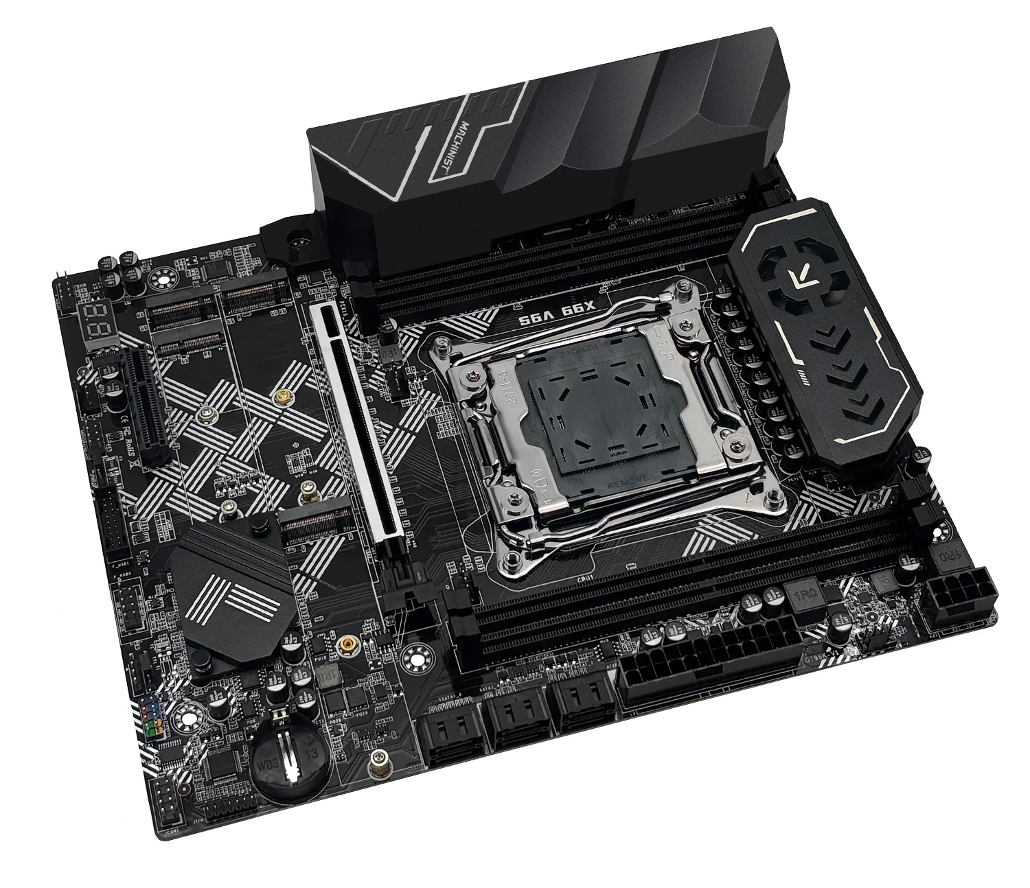
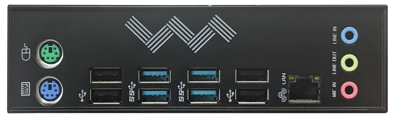
The first thing that stands out is the look and build quality—well above typical budget boards for this platform. Colors across the PCB are matched tastefully, and the integrated I/O shield adds a premium touch. Visually, these are among the best‑looking LGA2011‑3 boards.
The server‑grade Intel C612 chipset was chosen, so neither model is short on modern I/O. At long last, the many PCIe lanes on Xeon E5 are used properly. The lanes for all PCIe slots and all three M.2 slots come from the CPU (PCIe 3.0); the chipset lanes (PCIe 2.0) appear to be unused.

Power delivery uses a six‑phase design with two MOSFETs per phase. It employs the ISL6376 PWM controller, and the overall VRM configuration closely resembles what we’ve seen on Huananzhi boards like the X99‑QD4. MOSFETs: 3NA7R2 (52 A / 7.2 mΩ) on the high side (×6) and 3NA3R4 (75 A / 3.4 mΩ) on the low side (×6). This setup is well suited to mid‑range CPUs, but it’s still on the light side for high-core-count processors. Thanks to active cooling—a small fan running at a fixed 5 V—you can safely use CPUs up to approximately 135 W TDP.

Care also went into other details. The TPM 2.0 header sits next to the CMOS battery, so large graphics cards no longer block the module. You get four fan headers, and all of them are 4‑pin. Even the ubiquitous ALC897 audio codec features four dedicated filter capacitors, improving analog output quality.

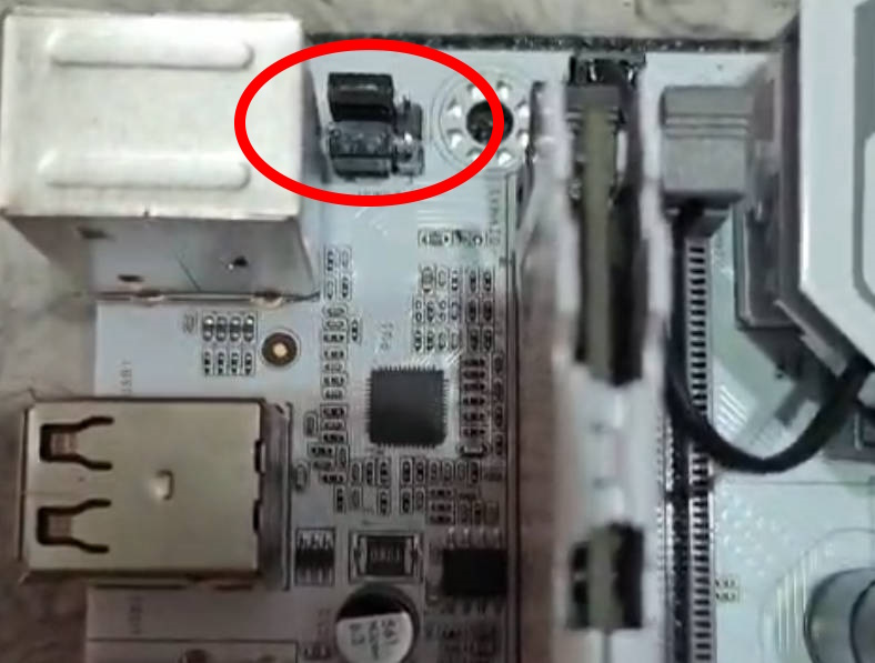
The developers didn’t overlook USB connectivity either. There are now two USB 2.0 headers and—most importantly—you can enable or disable port power while the PC is off. Several JPWR jumpers are provided for this: one next to the USB 3.0 header, and two more hidden under the plastic rear I/O shroud (you’ll need to remove it for access).

The icing on the cake is the working CPU power telemetry and a functional sleep mode (S3)—features many users of budget boards had all but forgotten.
BIOS Capabilities
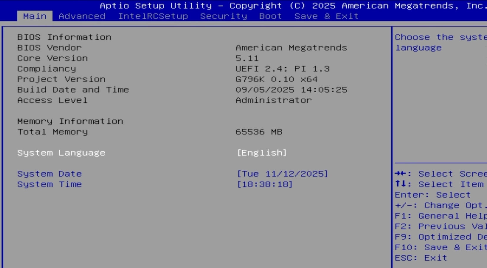
The board runs a familiar Aptio V‑based UEFI/BIOS. The firmware lacks a modern GUI and mouse support, but it includes virtually everything you need. Out of the box, you can adjust RAM timings, and both Resizable BAR and Above 4G Decoding work. Secure Boot is present, as is a configuration module for TPM 2.0 devices; the only missing piece is overclocking support for unlocked CPUs.
Unfortunately, the usual rough edges are here as well—an incorrect motherboard temperature sensor reading, quirky Smart Fan behavior, a huge number of options (some of which don’t work), and, oddly enough, no ECC support in the BIOS. ECC memory modules will still work, but only in non-ECC mode without error correction. While the stock firmware is fine for daily use, we recommend using an external fan controller or PWM hub for case fans rather than relying on Smart Fan.
It’s not a dealbreaker, but it is annoying: disabling CSM noticeably increases boot times. We hope this will be fixed in future BIOS versions.
Simple BIOS Flashing Guide (Windows)
| BIOS version & date | Ram Timings | ReBAR | Unlocked CPU OC | Turbo Boost unlock | Undervolt | Secure Boot & TPM2.0 | Notes & Link |
|---|---|---|---|---|---|---|---|
| (09/05/2025)X99 | + | + | - | - | - | + | Stock BIOS [Download] |
| (09/05/2025)X99 | + | + | - | + | -50 mV | + | Stock BIOS + TBU for v3 CPUs [Download] |
| (09/05/2025)X99 | + | + | + | - | - | + | Stock BIOS with overclocking capability for unlocked CPUs [Download] |
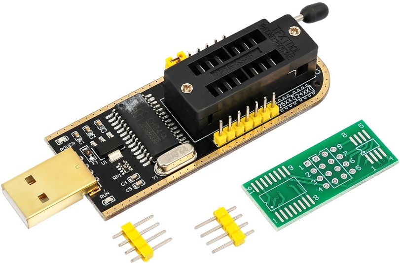
- Download Intel Flash Programming Tool (FPTW) 9.1.10 from this page.
- Open Command Prompt as Administrator.
- Place your BIOS file (
bios.binorbios.rom) in the FPTW directory. - In Command Prompt, navigate to the FPTW folder using the
cdcommand. - Back up first:
fptw64 -d backup.bin - Flash the BIOS:
fptw64 -f bios.bin
Notes: Replace bios.bin with the actual name of your BIOS file.
After flashing, we recommend resetting settings or clearing CMOS.
Frequently Asked Questions
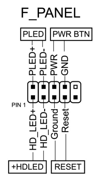
How do I connect the front panel?
The board won’t boot—black screen, etc. What should I do?
See our article about the most common LGA2011‑3 issues.
Is there a manual available (PDF)?
Download the official Machinist manual here (V9s) and here (U9).
Is Turbo Boost Unlock possible on this board?
Yes. You can perform the unlock using S3TurboTool by following our guide, or wait for a ready‑made BIOS with the unlock applied.
Where can I find drivers for this board?
You can find up-to-date drivers for LGA2011‑3 platforms on this dedicated page.
Which TPM 2.0 module is compatible with this board?
You need an ASUS 14‑pin LPC TPM 2.0 module—for example, this one.

Conclusion
OldRigRevive Review
5.0
4.0
4.6
4.3

Written by
Senior Hardware Specialist proving you don't need top-tier gear to game. Expert in smart upgrades and budget-friendly PC restoration.
Hello, I’m Sebastián, I would like to know How to active wake on lan on the bios. I wasn’t able to find it. Thank you
Check IntelRCSetup > PCH Configuration > Networking. There should be a Wake On LAN option. If it is not there, you may need to open it via AMIBCP.
“Hello,I have two Machinist X99-U9 motherboards paired with Xeon E5 v3 processors. In the BIOS, I can see the ‘Overclocking Features’ section with voltage adjustment options.My questions are:Do these voltage control (Undervolting) options work natively on the stock BIOS with Xeon v3 CPUs, or is a modded BIOS (with injected EFI drivers) still required to apply these changes effectively?Does the stock BIOS support Turbo Boost Unlock (TBU) for all cores by default, or does it require the typical microcode removal and ‘S3TurboTool’ / ‘V3.efi’ modification?I would appreciate any clarification on whether a custom BIOS flash is necessary to fully utilize undervolting and TBU on this specific board. Thank you!”
Hello!
I’m not 100% sure specifically about this board, and I also don’t know which exact BIOS version you have. Sometimes Chinese sellers flash modified BIOS versions with Turbo Unlock already integrated before shipping.
However, on most Chinese X99 motherboards, the voltage and multiplier settings visible in the BIOS often do not work properly. Usually, undervolting and Turbo Boost Unlock still need to be done manually — either by using the common EFI/microcode modifications (V3.EFI, S3TurboTool, etc.) or by flashing a BIOS that already has the unlock integrated.
So in most cases, if you want guaranteed working undervolting and full all-core turbo behavior, a modded BIOS is still required.
You can also verify whether undervolting and TBU are actually working on your system by checking CPU clocks and voltages in HWiNFO64 under load.
I recently purchased this motherboard (x99-u9) and used Xeon processor and three 8 GB ECC RAM modules. So far, this has been the most confusing, picky, hard to configure motherboard with inadequate documentation I’ve ever worked with.
The DIMM slots on the board are labeled from left to right as A1, B1, C1, and D1. And, the M.2 SSD slots are labeled SSD2 and SSD3 on the left, and SSD1 on the right. However, The manual shows the exact opposite, with NVMe 1 and 2 on the left and NVMe 3 on the right. This makes it very difficult to know where everything should be installed.
It took me a long time to figure out which RAM slots would actually work. Every time the system failed to POST, I had to remove everything, clear the CMOS, and start over with another memory configuration.
Eventually, I found that a single RAM module would boot only in the C1 slot. After more trial and error, I managed to get three modules working in B1, C1.
I then tried installing Windows 11 with 16Gb ecc and TPM2.0 installed. The installation produced multiple errors, and required many workaround, regedit tricks to continue. After every installation, Windows could not find the boot partition. ChatGPT suggested the issue could be related to the storage controller, an outdated BIOS, or a problem with UEFI support where Windows cannot properly recognize the board storage system.
After several failed attempts, I switched to Windows 10 with legacy boot. Although Windows 10 installed, the system was extremely slow, taking about five minutes just to boot and reach the login screen. The installation also appeared to be corrupted or unstable.
for new attempt, I tried installing the third RAM module, but I was back to square one. The motherboard would no longer power up until I cleared the CMOS again and experimented with different memory configurations.
Has anyone successfully built a system with this motherboard? Can someone tell me:
Which DIMM slots should be populated when using one, two, or three ECC memory modules?
Which M.2 slot should be used as the primary boot drive?
Hi!
First off, don’t rely too much on the printed manual or the labels on the motherboard itself — Chinese manufacturers are notorious for swapping silkscreen markings between revisions or simply including manuals from completely different boards!
Here is what I can recommend:
1. RAM Slots & The “Eraser Trick”
Theoretically, the LGA 2011-3 platform uses a 4-channel memory controller integrated directly into the Xeon CPU. Ideally, it shouldn’t matter which specific slots you populate with 1, 2, or 3 RAM sticks — the motherboard will simply enable whatever channels it detects.
However, since your board randomly fails to POST, this often points to a poor contact issue between the CPU and socket, or dirty/oxidized contacts on the RAM sticks themselves.
2. M.2 Slots
On this board, all M.2 NVMe slots pull their PCIe 3.0 lanes directly from the Xeon processor. Unless Machinist released a new revision with a SATA-based M.2 port, any of these slots should work fine as your primary boot drive.
3. Windows & Boot Issues
The “lost” boot partition issue is likely caused by a conflict between CSM and UEFI modes. For Windows 11, it is best to use pure UEFI mode with GPT partition style, as the old Legacy (CSM) mode on X99 can cause severe slowdowns and bootloader corruption.
Make sure your Boot option is set to “UEFI Only”:
Advanced > CSM Configuration > Boot option filter = UEFI onlyTo help troubleshoot this further, could you check:
Note: There is always a chance of a hardware defect with the board, RAM sticks, or one of the CPU’s memory channels, but try cleaning the contacts with an eraser and checking your UEFI settings first!