Table of Contents
One of the most common complaints about Chinese LGA2011‑3/X99 boards is the lack of manual memory timing controls in the BIOS. The functionality is almost always present inside the firmware — it’s just hidden and unreachable from the normal Setup menus. This guide walks through exposing it.
This is the text version of Koshak’s video guide, available at this link (YouTube).

⚠️ Full responsibility disclaimer. As always, results aren’t guaranteed and you take full responsibility for what you do to your own board.
Be aware that if anything goes wrong, flashing a bad BIOS will most likely brick the board; recovery will only be possible with a hardware programmer — there is no software fallback once a bad image is flashed.
Who this is for
Boards using AMI Aptio V firmware on Chinese X99 (LGA2011‑3) motherboards — Huananzhi, Jingsha, Kllisre, Machinist, Qiyida, JGINYUE, and the many rebrands/clones that share the same firmware bases. Many of these boards ship from the same handful of base BIOS images, which is why the exact same QuestionIDs and hex patterns from this guide (0xC05/0xC06, 6710/9000) turn up on boards from completely different brands.
Why this works
On AMI Aptio V firmware, the BIOS “Setup” user interface is a set of forms described by IFR (Internal Forms Representation) inside the Setup/Platform module. Each control has a QuestionID, and AMITSESetupdata tells the Text Setup Engine (TSE) which forms are visible and how they are linked in the menu tree. On many Chinese X99 boards, the “Memory Timings & Voltage Override” form exists in the firmware but is simply not linked to any visible menu (and/or its access is restricted), so you can’t reach it.
- This guide extracts the relevant modules (Platform and AMITSESetupdata), reads IFR to find the correct QuestionIDs, and edits a few 16‑bit identifiers so the hidden form is linked under “Memory Configuration”.
- We are not adding new code; we are exposing an existing form by changing menu routing/visibility. That’s why it works across many similar BIOS bases, provided you locate the correct IDs for your build.
- Exact IDs and offsets vary between BIOS revisions. That’s why the process starts with IFR parsing to discover your own QuestionIDs before patching byte patterns in AMITSESetupdata and Platform.
Before you start
- Back up your full BIOS image (16 MB) using any method supported by your board—whether via software (Intel FPT, AFUWIN, AFUDOS) or an external SPI programmer.
- Confirm your flashing method in advance. Ensure you can both read from and write to your chip using your tool of choice before applying any mods.
- Download the required software.
Required software
| Tool | Purpose | Version used in this guide |
|---|---|---|
| AMIBCP 5 | Browse the Setup menu tree, verify before/after state | 5.02.0034 |
| Hex editor | Patch the extracted modules | HxD (any reliable hex editor works) |
| UEFITool | Extract/replace modules inside the BIOS image | 0.28.0 |
| IFRExtractor | Dump IFR forms to text, find QuestionIDs | 0.3.6 |
You can find all the necessary software in this Telegram channel.
Step 1 — Confirm the memory timing menu exists but is hidden
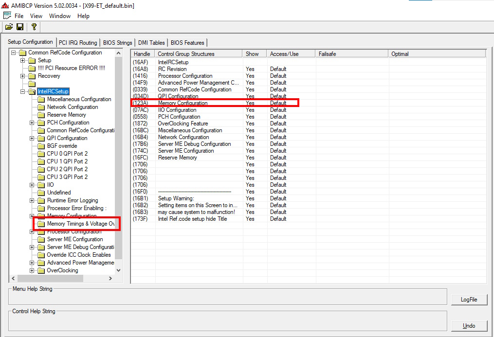
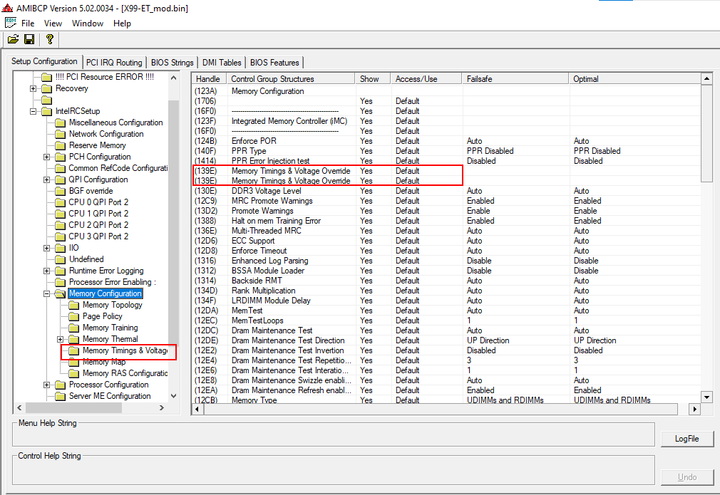
In AmiBCP, open your BIOS dump, expand the “IntelRCSetup” node and you’ll see the pattern typical for Chinese firmware: the “Memory Timings & Voltage Override” item is visible under “IntelRCSetup”, but access to it is blocked — it’s not reachable from the main menu.
Our task will be to move “Memory Timings & Voltage Override” into the “Memory Configuration” menu.
Step 2 — Extract the two modules with UEFITool
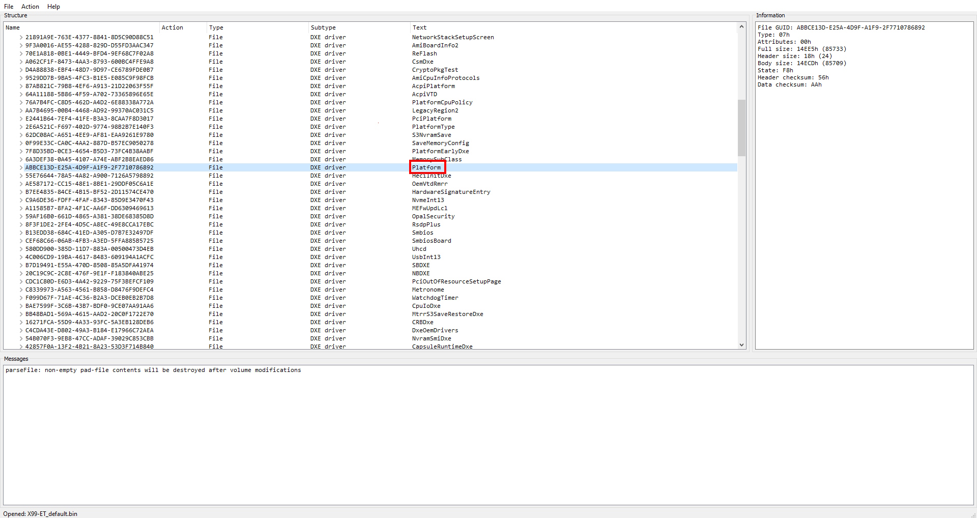
Open your BIOS dump in UEFITool. We’re interested in two modules: “Platform” and “AMITSESetupdata”. Both modules are under “Intel Image” > “Bios Region” > the second‑to‑last expandable branch.
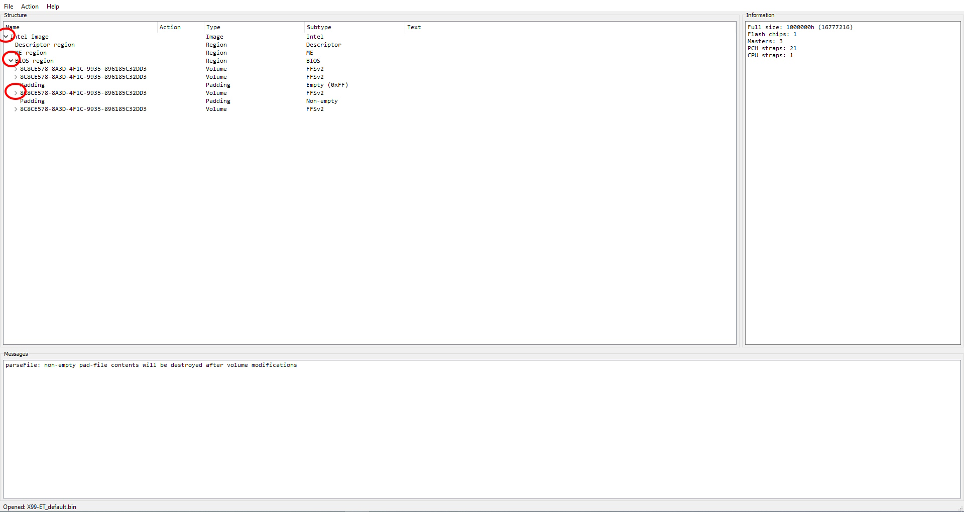
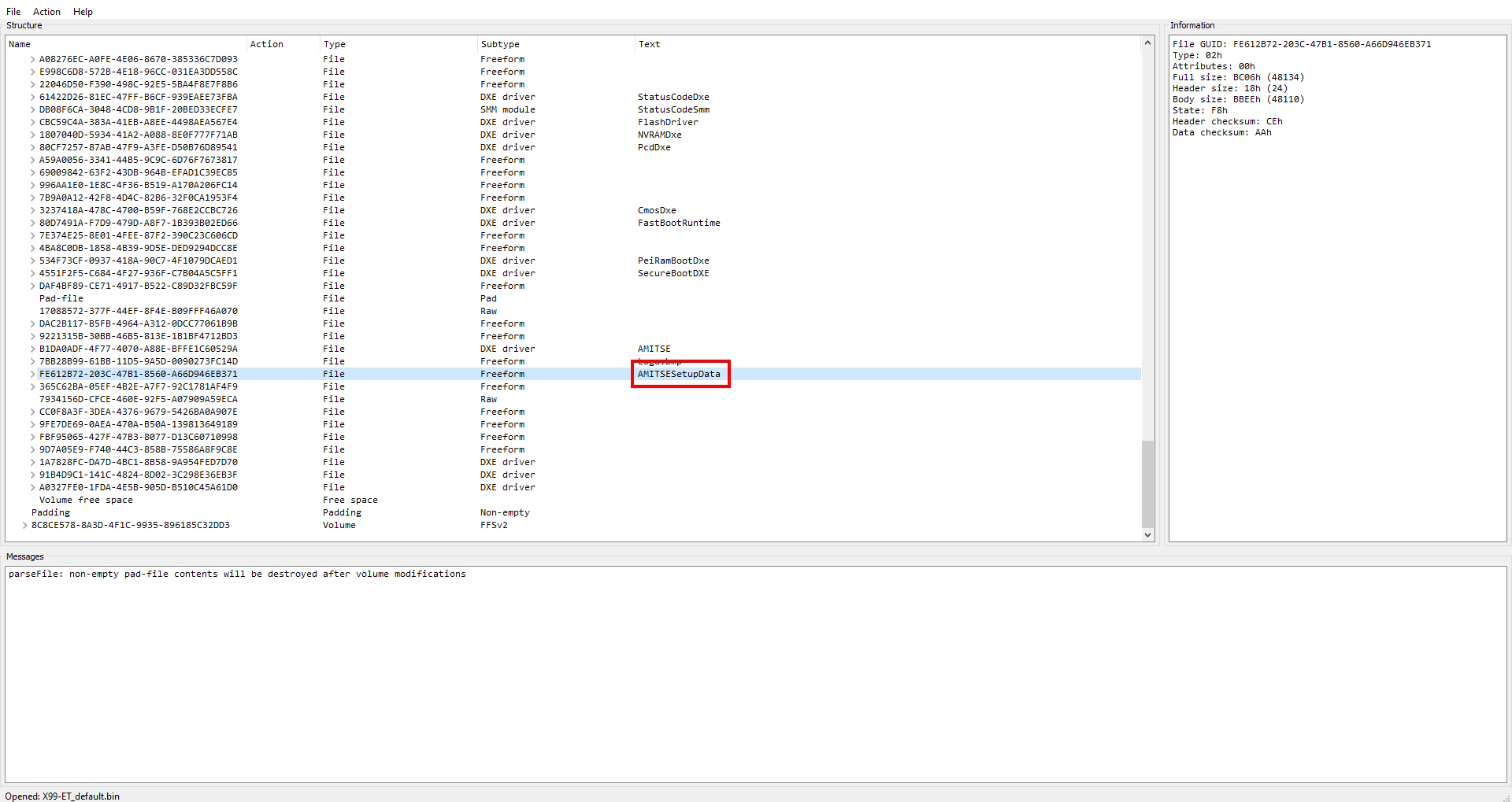
Some UEFITool versions/board firmware label the top‑level branch “UEFI image” instead of “Intel Image”. If you don’t see “Intel Image,” look for “UEFI image” — it’s the same thing under a different label.
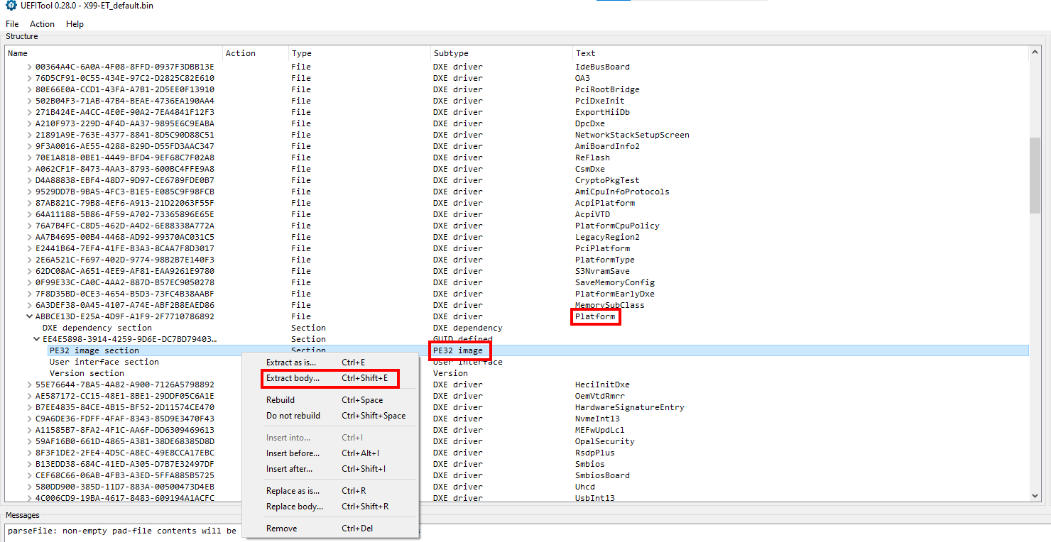
Find the “Platform” module, expand it until you reach “PE32 image”. Then right‑click and choose “Extract body”. Save the file as “pl.bin”.
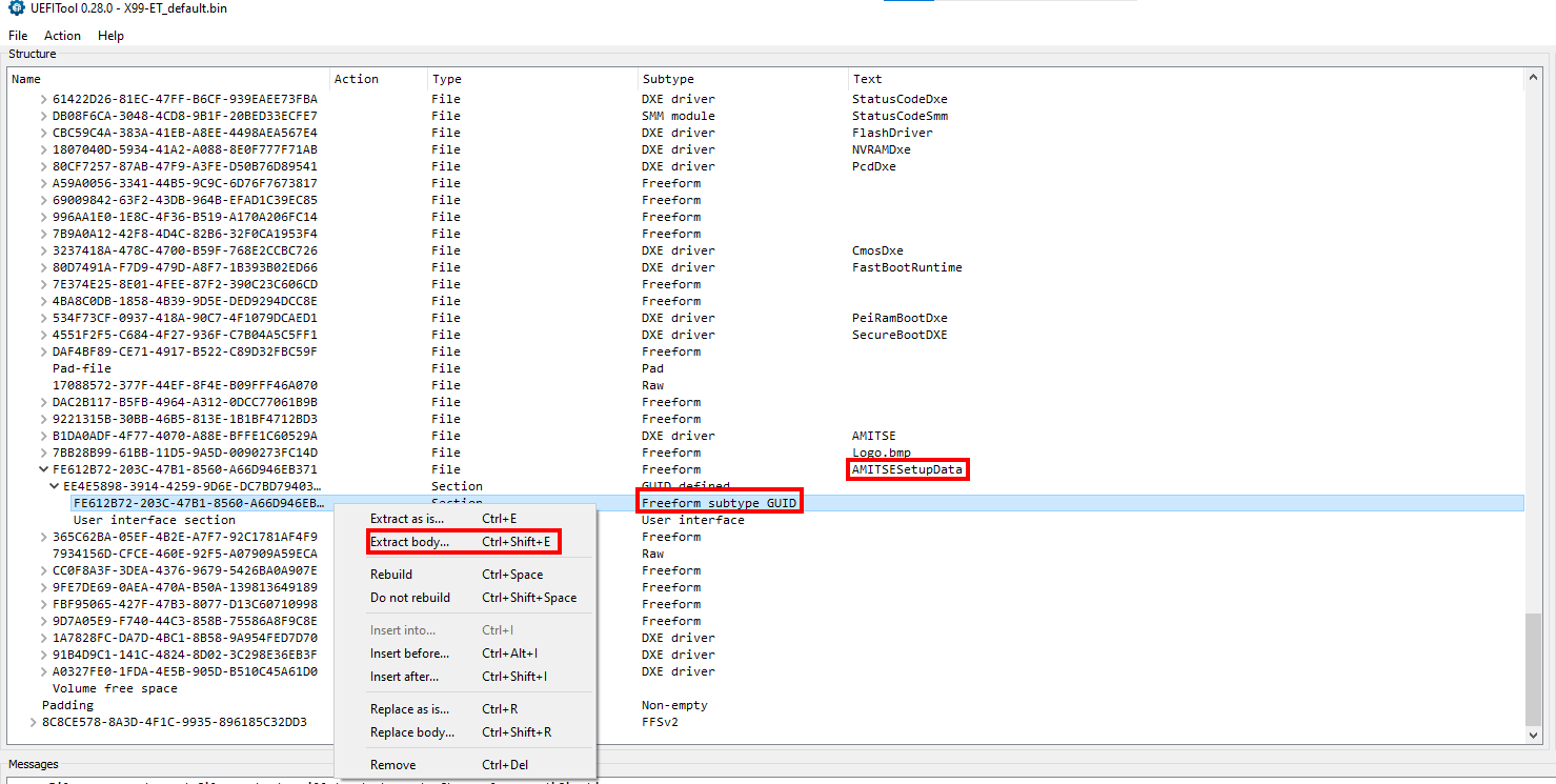
Find the “AMITSESetupdata” module, expand it until you reach “Freeform subtype GUID”. Then right‑click and choose “Extract body”. Save the file as “fe.bin”.
It’s better not to close UEFITool — we’ll need it again in Step 5.
Step 3 — Find your QuestionIDs with IFRExtractor
Launch IFRExtractor and open the “pl.bin” file you saved in the previous step. After you press “Extract”, the utility will save a text file called “pl IFR.txt” in the same folder.
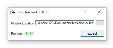
Open it and find the string “memory frequency”. It may appear several times in the file; we’re interested in the first occurrence.
Note the QuestionID value (in our example, it is 0xC05). We’ll also need the next “QuestionID”, in our case 0xC06.
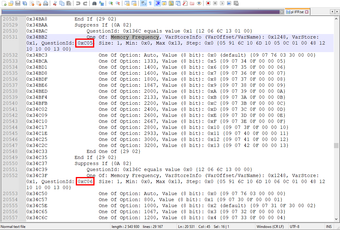
If you see 0xC05 and 0xC06 on your board too, you’re most likely on one of the common Chinese BIOS bases (shared by many Jingsha/Kllisre‑derived boards) — and the rest of this guide should apply almost byte‑for‑byte.
Converting the QuestionID to the hex pattern you’ll search for
You need each QuestionID as a byte‑swapped, 4‑digit hex string:
- Pad the QuestionID to 4 hex digits (leading zero if needed): 0xC05 → 0C05.
- Split into byte pairs: 0C 05.
- Reverse the byte order: 05 0C.
- Concatenate: 050C.
A few examples for clarity: 0xC36 → 360C; 0xC78 → 780C; 0xCB3 → B30C.
We’ll use a table to keep track of these values—make sure to create your own table and fill it in with the exact IDs you discover for your BIOS, so you don’t get mixed up later.
| Cell | What it is | Value |
|---|---|---|
| V1 | QuestionID #1 (0xC05, converted) | 050C |
| V2 | QuestionID #2 (0xC06, converted) | 060C |
Step 4 — Patch both modules in a hex editor
Open both of the modules you saved earlier: pl.bin and fe.bin.
4a. Patch fe.bin first
Search for the hex value “81000000”.
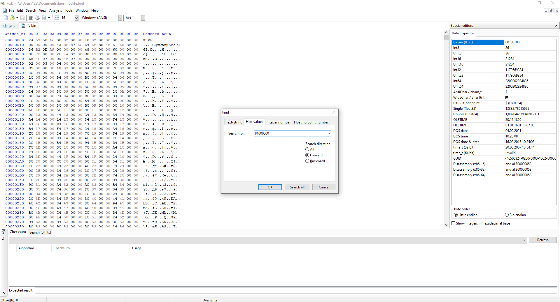
Look at the 12 characters to the right of the found value. In our case, these are 6710, 9000 and 1D00 (your values may be different).
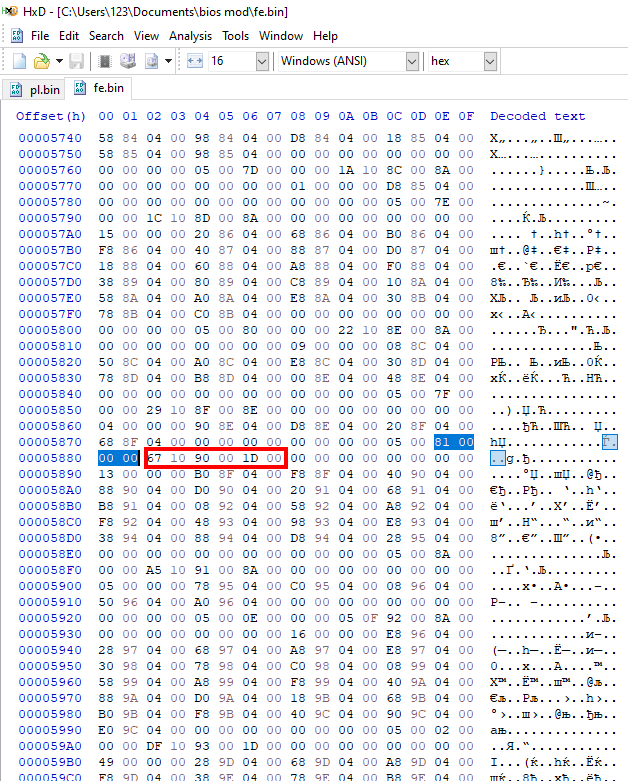
Record 6710 in your tracking table. Next to it, add 6910—calculated by adding 0x200 to 6710. You will also need to log 9000 (no math required here) and 1D00 for the upcoming steps.
💡 How Hex Addition Works (+0x200)
Hexadecimal (base-16) uses numbers 0–9 and letters A–F. Adding 0x200 simply increases the second digit from the left by 2:
6710+200=6910(7 + 2 = 9)6D10+200=6F10(D + 2 = F, where D=13 and F=15)
📌 Tip: If you are unsure, open Windows Calculator, switch it to Programmer mode, select HEX, and do the addition there.
Same data as a table (values V1–V2 carried over from Step 3, plus the new ones from this step):
| Cell | What it is | Value |
|---|---|---|
| V1 | QuestionID #1 (0xC05, converted) | 050C |
| V2 | QuestionID #2 (0xC06, converted) | 060C |
| V3 | Found value in fe.bin (right of 81000000) | 6710 |
| V4 | V3 + 0x200 | 6910 |
| V5 | Second found value in fe.bin (right of 81000000) | 9000 |
| V6 | Third found value in fe.bin (right of 81000000) | 1D00 |
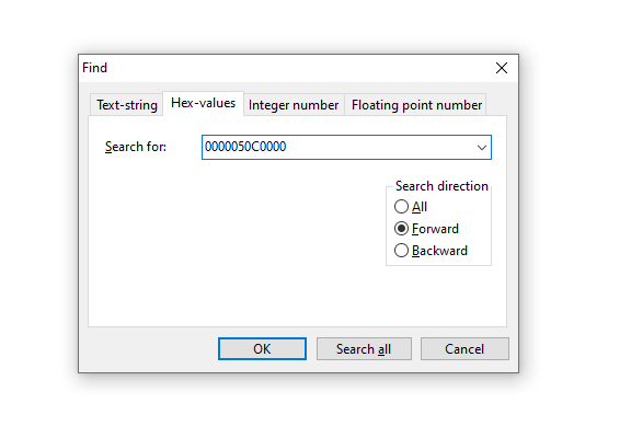
Go back to the hex editor. Now search for the previously saved value 050C (Cell V1), but first convert it to 0000050C0000 by adding four zeros at the beginning and four zeros at the end.
Now carefully look at the image below and make the areas next to the found hex value match it exactly. Note that the values highlighted in red are taken from our table, while the values highlighted in blue should be set exactly as in the screenshot, regardless of your board.
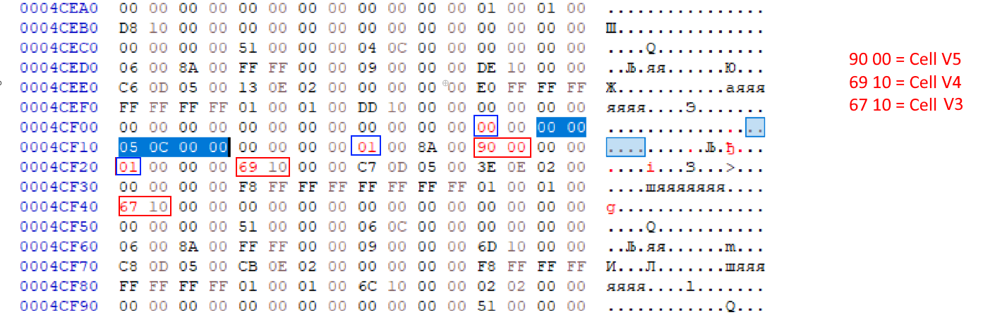
Now do the same operation for the value 060C (Cell V2), which we also convert to 0000060C0000.

Then search for 0000050C0000 (Cell V1 with four zeros before and four zeros after it) again. This time, pay attention to the four characters highlighted with a green frame: 8A00. Add them to the table.
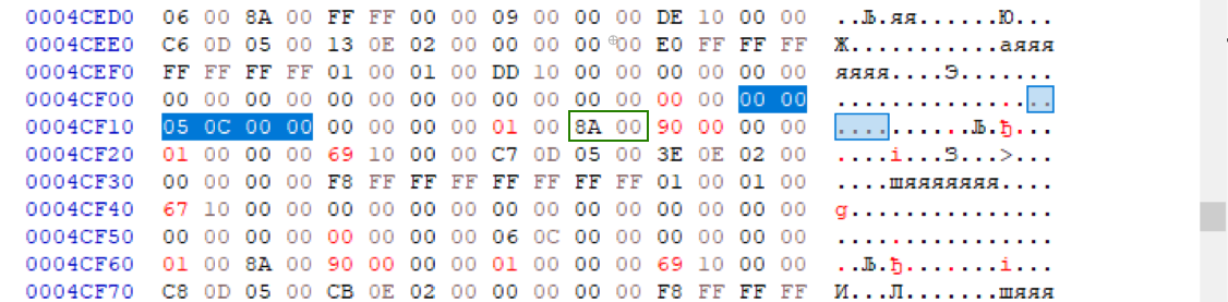
| Cell | What it is | Value |
|---|---|---|
| V1 | QuestionID #1 (0xC05, converted) | 050C |
| V2 | QuestionID #2 (0xC06, converted) | 060C |
| V3 | Found value in fe.bin (right of 81000000) | 6710 |
| V4 | V3 + 0x200 | 6910 |
| V5 | Second found value in fe.bin (right of 81000000) | 9000 |
| V6 | Third found value in fe.bin (right of 81000000) | 1D00 |
| V7 | Green‑frame value (found searching Cell V1 with four zeros before and four zeros after it) | 8A00 |
Remember we searched for the hex value “81000000”? Do that again.
To the right of the found value, we still have 6710 (Cell V3), 9000 (Cell V5) and 1D00 (Cell V6). Replace 1D00 (Cell V6) with 8A00 (Cell V7).

That’s it for the “fe.bin” modifications; save your changes and move on to “pl.bin”.
4b. Patch pl.bin
Search for the hex value “050C” (Cell V1). It will occur many times in the file; we need the instance that is preceded by characters similar to our “67106910” (Cell V3 and V4).
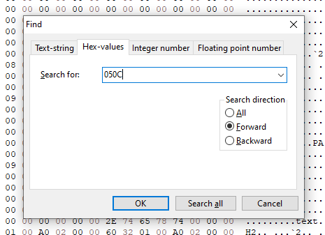
Keep in mind that you are unlikely to see these exact values. You should select the entry that most closely resembles your own extracted values from your table.
After some searching, we find the right section:
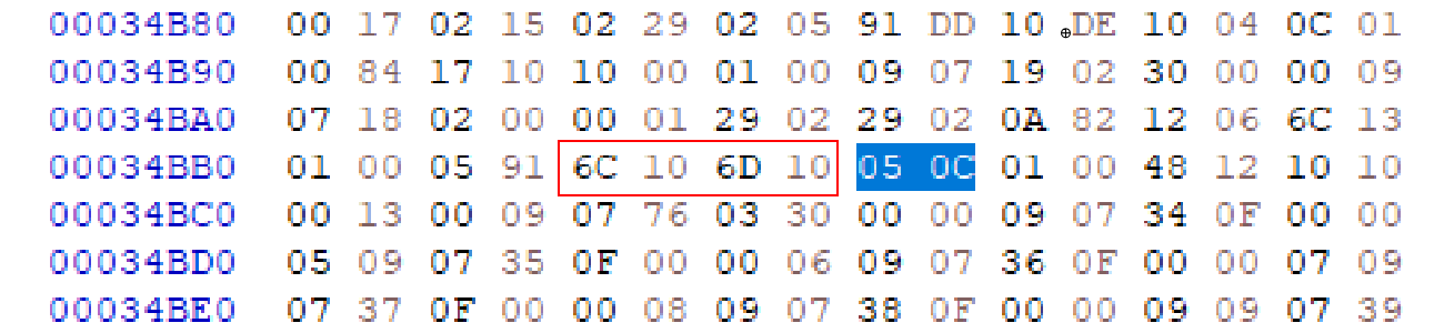
Replace the characters with “67106910” (Cell V3 and V4):

Now repeat the entire search‑and‑replace procedure, but for the hex value “060C” (Cell V2):

That’s it for the “pl.bin” file. Save your changes.
Step 5 — Reinsert the patched modules with UEFITool
Find the two modules again: “Platform” and “AMITSESetupdata”.
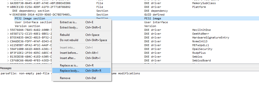
For the “Platform” module, expand it until “PE32 image”. Then right‑click and choose “Replace body”. Select the recently modified “pl.bin”.
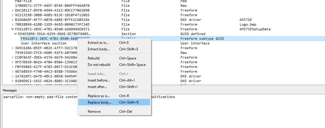
For the “AMITSESetupdata” module, expand it until “Freeform subtype GUID”. Then right‑click and choose “Replace body”. Select the recently modified “fe.bin”.
Now save your mod BIOS under a new name (File > Save image file) — don’t overwrite your original dump.
Step 6 — Verify in AMIBCP before flashing
Open the BIOS you just saved and make sure that the memory timing control menu has appeared and is accessible from the “Memory Configuration” item.
That’s it. All that remains is to flash your mod BIOS using any method suitable for your board.
Post‑flash checks
- Power off completely, clear CMOS (jumper or battery), then power on and enter BIOS.
- Load Optimized Defaults, Save & Exit, then re‑enter the BIOS.
- Navigate to Advanced → Memory Configuration and verify that “Memory Timings & Voltage Override” is now visible and selectable.
- Open it and confirm that timing fields (e.g., tCL, tRCD, tRP, tRAS, Command Rate) are present and editable — not just a frequency dropdown.
- If the menu is missing or enters a blank page, revert to your backup BIOS and re‑check the IDs/offsets you edited (see Troubleshooting below).
- After applying any custom timings and saving changes in BIOS, boot into the OS and check if your new values were actually applied using tools like CPU-Z (Memory tab) or AIDA64. Once verified, run a stability test to ensure your system is completely stable.
Troubleshooting
I can’t find a “Platform” module in UEFITool.
Check under a branch called “UEFI image” instead of “Intel Image” — some firmware/UEFITool combinations use that label instead. If neither exists, your board may use a different firmware base than the one this guide targets.
The menu appears after flashing, but it only shows a frequency dropdown — no real timings.
You likely linked the wrong form. Go back to Step 3 and confirm you used the first “memory frequency” match in the IFR dump.
AMIBCP shows the Setup Configuration tab as missing/corrupted after patching.
This points to a misaligned hex edit — most often a wrong byte count when padding/replacing one of the search patterns. Re‑do Step 4 from a fresh copy of the extracted modules rather than trying to patch on top of a partially‑edited file.
My board’s found values don’t match the ones in the screenshots (e.g. 6D10 instead of 6710).
Expected — these values are specific to your BIOS build. Use whatever your hex editor actually finds, apply the +0x200 rule to get the second value, and carry your own values through the rest of the guide instead of the example ones.
The system won’t POST after flashing.
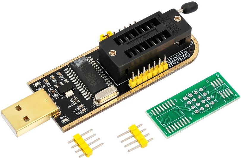
Clear CMOS again (jumper or battery pull, full power disconnect for a minute). If it still won’t boot, restore your backup with a hardware programmer (e.g. CH341A) — this is the only recovery path once the board is bricked.
Credits and further reading
- Original video guide: Koshak, YouTube
- Pre‑patched BIOS images for many X99 models: Koshak1013/HuananzhiX99_BIOS_mods on GitHub
- Base guide in Russian: e5450.com

Written by
Senior Hardware Specialist proving you don't need top-tier gear to game. Expert in smart upgrades and budget-friendly PC restoration.