Chinese X79 Motherboard BIOS Mod: Unlocking RAM and CPU Multiplier Overclocking
This guide is a practical, English-language walkthrough for modifying the BIOS of Chinese-made LGA2011 (X79) motherboards. It covers two separate mods: unlocking RAM overclocking and unlocking CPU overclocking via the multiplier.
⚠️ Read before you start. Everything described below is done entirely at your own risk. A mistake at any step can “brick” the motherboard, and the only way back at that point is reflashing the chip with an external SPI programmer. Always keep a copy of your original, unmodified BIOS dump before you touch anything.
Table of Contents
Why this is needed / how it works
Chinese X79 / LGA2011 boards (Huananzhi, Kllisre, Jingsha, Machinist, PlexHD/X79T, and countless rebrands) almost universally run on BIOS firmware built with the American Megatrends (AMI Aptio IV) framework. Manufacturers routinely ship these boards with memory-overclocking and CPU-multiplier-overclocking options artificially disabled in the firmware, even though the underlying reference code from Intel fully supports both. Because nearly all of these boards share the same AMI codebase, the same patching technique works across almost the entire line-up — you’re not hacking around a limitation, you’re simply re-enabling functionality that Intel’s own reference BIOS module already contains but the vendor switched off.
The mod works by locating the specific firmware module (a PE32 executable embedded inside the BIOS image) responsible for a given feature, then flipping a handful of bytes inside it that control a conditional check gating that feature.
Before you start editing, make sure your board’s BIOS genuinely doesn’t respond to changes in memory frequency and CPU multiplier. By now, many manufacturers already ship firmware with these patches applied by default.
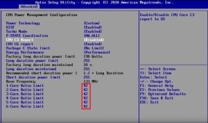
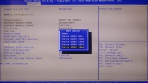
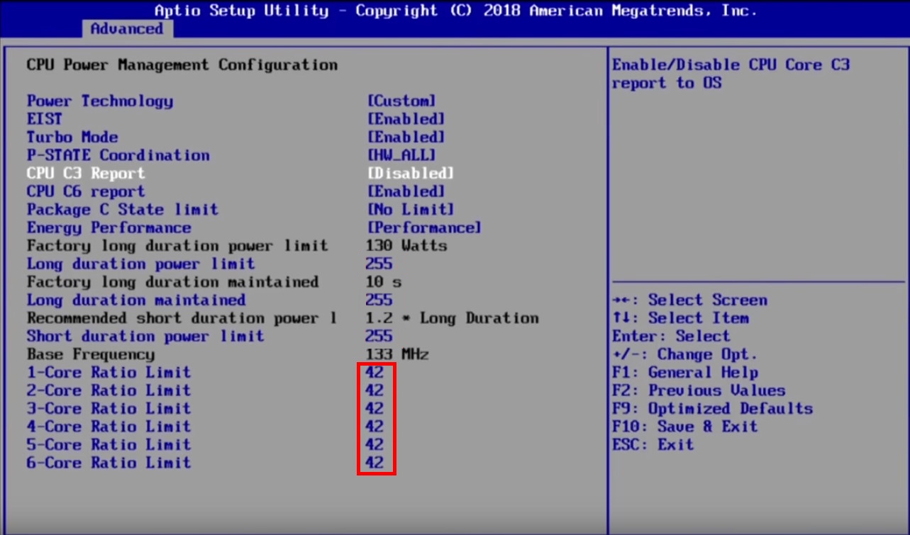
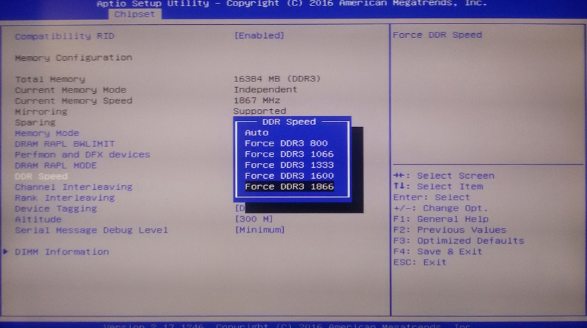
CPU overclocking is done from the Advanced → CPU Power Management Configuration menu; the multiplier for each core is set individually in the Core Ratio Limit field (these fields only appear once the CPU is unlocked). Memory overclocking is done from the Chipset → North Bridge menu, in the DDR Speed field.
Before you start
Back up your full BIOS image (8 MB) using any method supported by your board — either using software tools (Intel FPT, AFUWIN, AFUDOS) or an external SPI programmer.
Confirm your flashing method in advance. Ensure you can both read from and write to your chip using your tool of choice before applying any mods.
Download the required software.
Must-have Tool
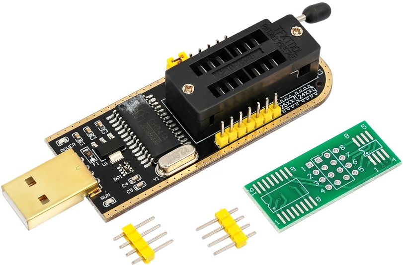
Working with BIOS mods? The CH341A programmer is essential. It lets you write SPI BIOS chips directly and helps recover bricked devices. For its price, it's the cheapest insurance for your hardware.
Before modifying anything, pull a full dump of the BIOS currently installed on your board and put it somewhere safe. This is your emergency recovery copy — if a flash goes wrong, this is what you reflash to get back to a working state (via an SPI programmer, if the board no longer boots).
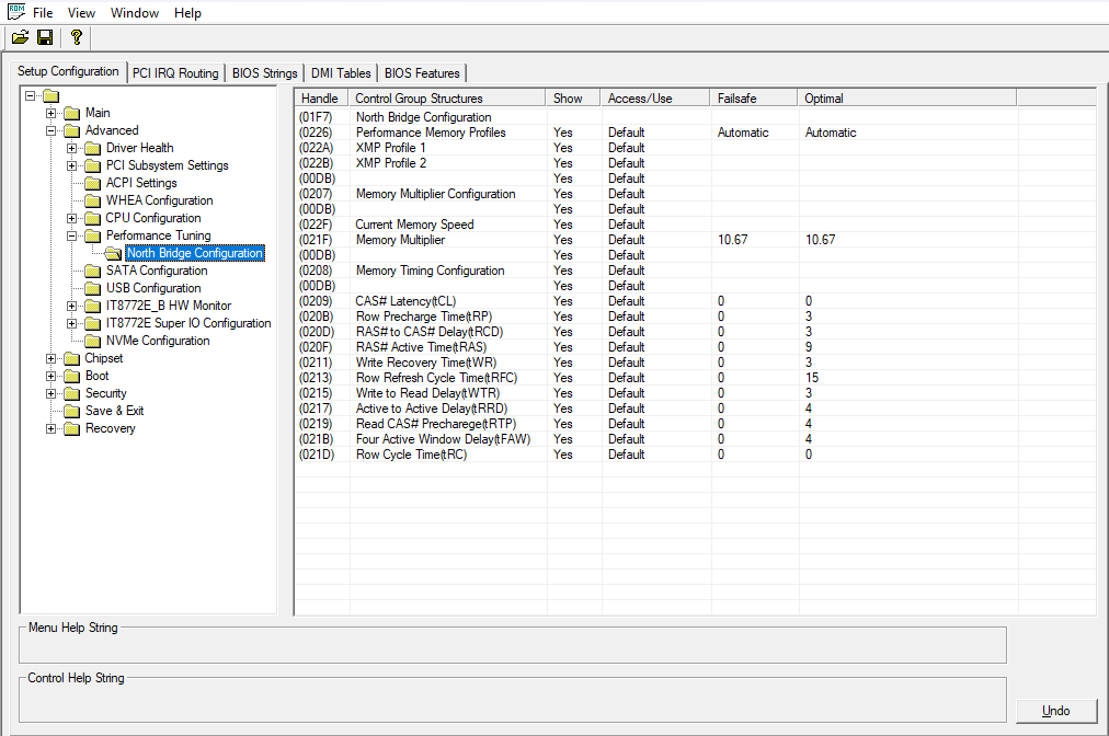
Before applying the memory-frequency unlock patch, open your BIOS in AMIBCP and check whether it already has a hidden timings/memory-frequency menu. Go to the Setup Configuration tab, expand Advanced, and check for a Performance Tuning entry containing a North Bridge Configuration menu. If you see a timings menu like the one in the screenshot below, your BIOS doesn’t need the memory patch at all (although applying it won’t cause any harm) — you simply need to unhide that menu by following this guide.
Part 1 — Unlocking RAM overclocking
This mod re-enables manual memory frequency control that the vendor locked out in the BIOS setup menu.
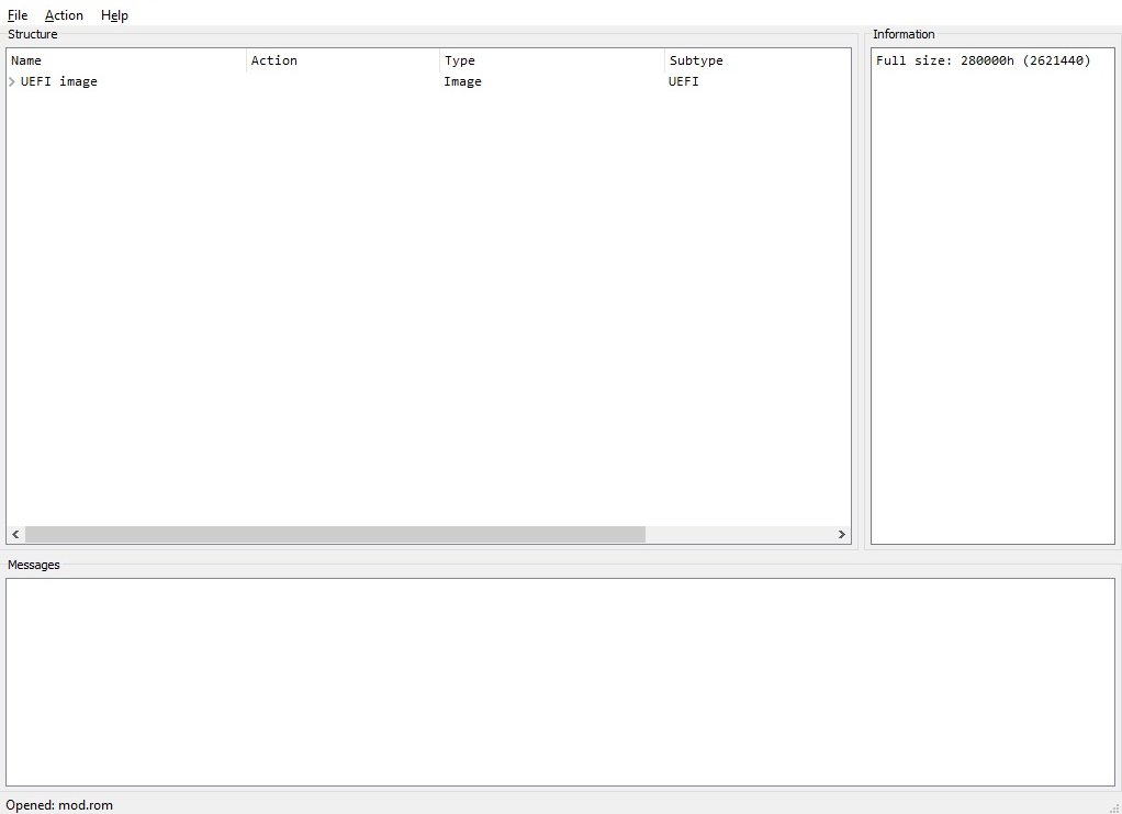
Once you have your safety dump, rename the working copy you’re about to edit to something memorable, e.g. mod.rom (or .bin, matching the extension your dump tool produced), and open it in UEFITool.
Opening the BIOS dump file in UEFITool.
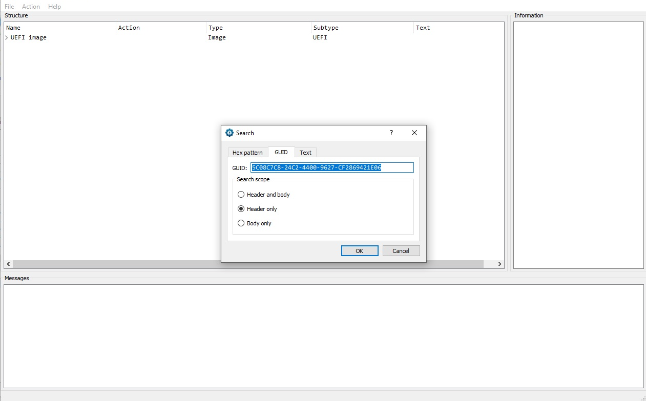
With your dump open in UEFITool, press Ctrl+F to open the search dialog. Switch to the GUID tab and search for:
5C08C7C8-24C2-4400-9627-CF2869421E06
Searching by GUID — the RAM overclocking module.
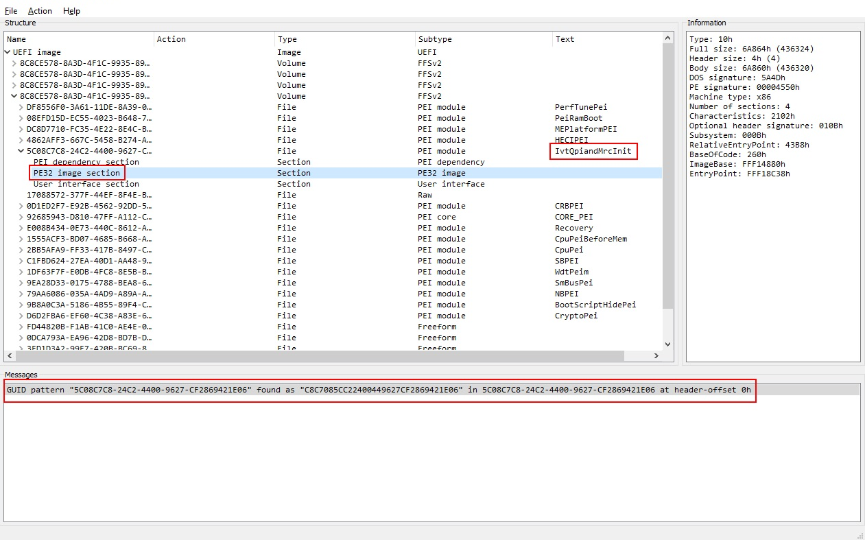
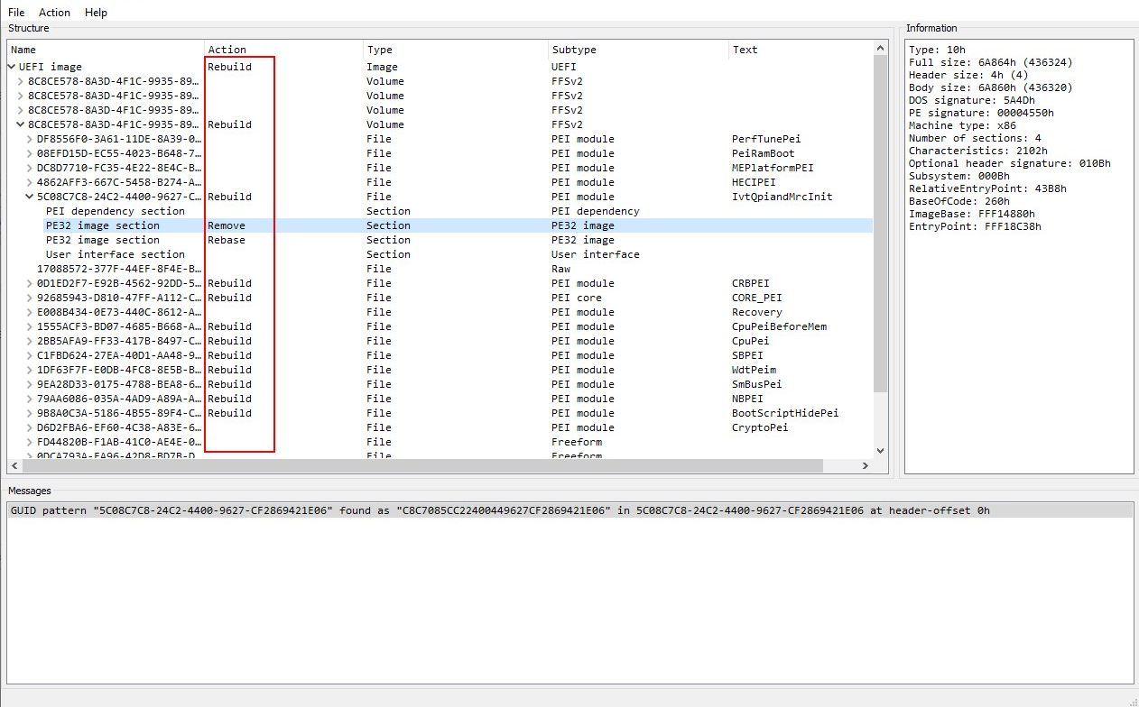
Click OK — UEFITool will report a successful match. Double-click the result at the bottom of the window, then expand the tree that appears. You’re looking for the PE32 image located inside the IvtQpiAndMrcInit module. The PE32 image sitting inside the IvtQpiAndMrcInit module.
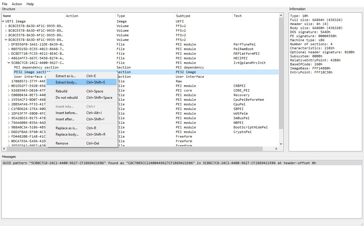
Right-click that PE32 image entry and choose Extract body. Save it with an easily recognizable name, e.g. ram. Right-click → Extract body, and save the file as “ram”.
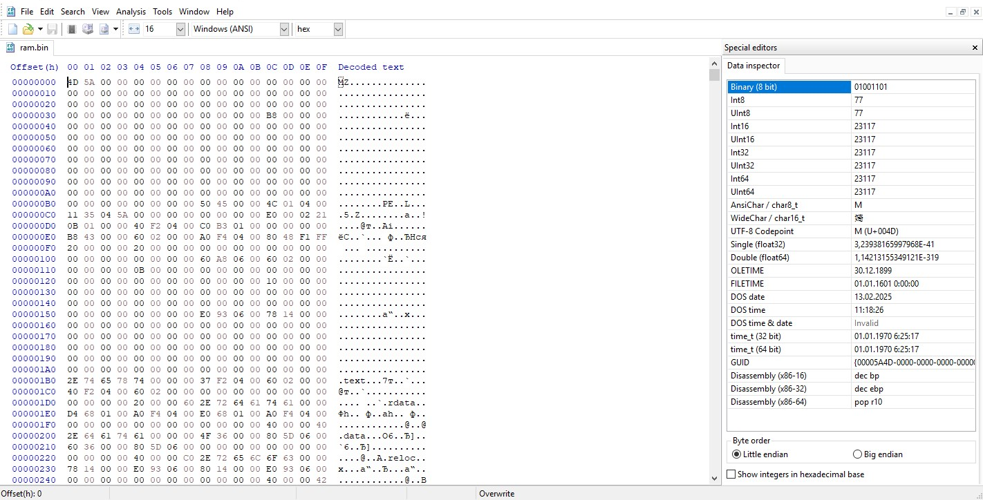
Open the extracted ram file in your hex editor. The extracted module opened in the hex editor.
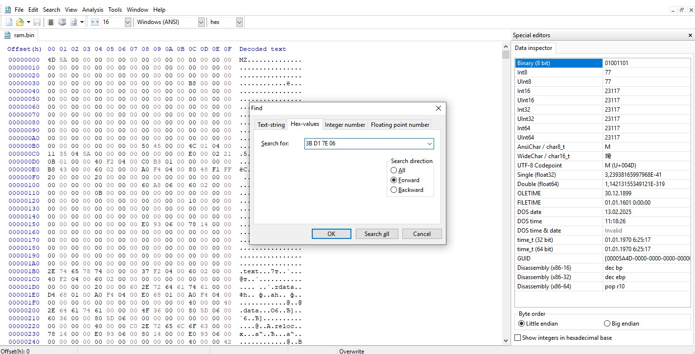
Press Ctrl+F, switch to the HEX-values search mode, and search for:
3B D1 7E 06
Searching for the byte pattern that gates RAM overclocking.
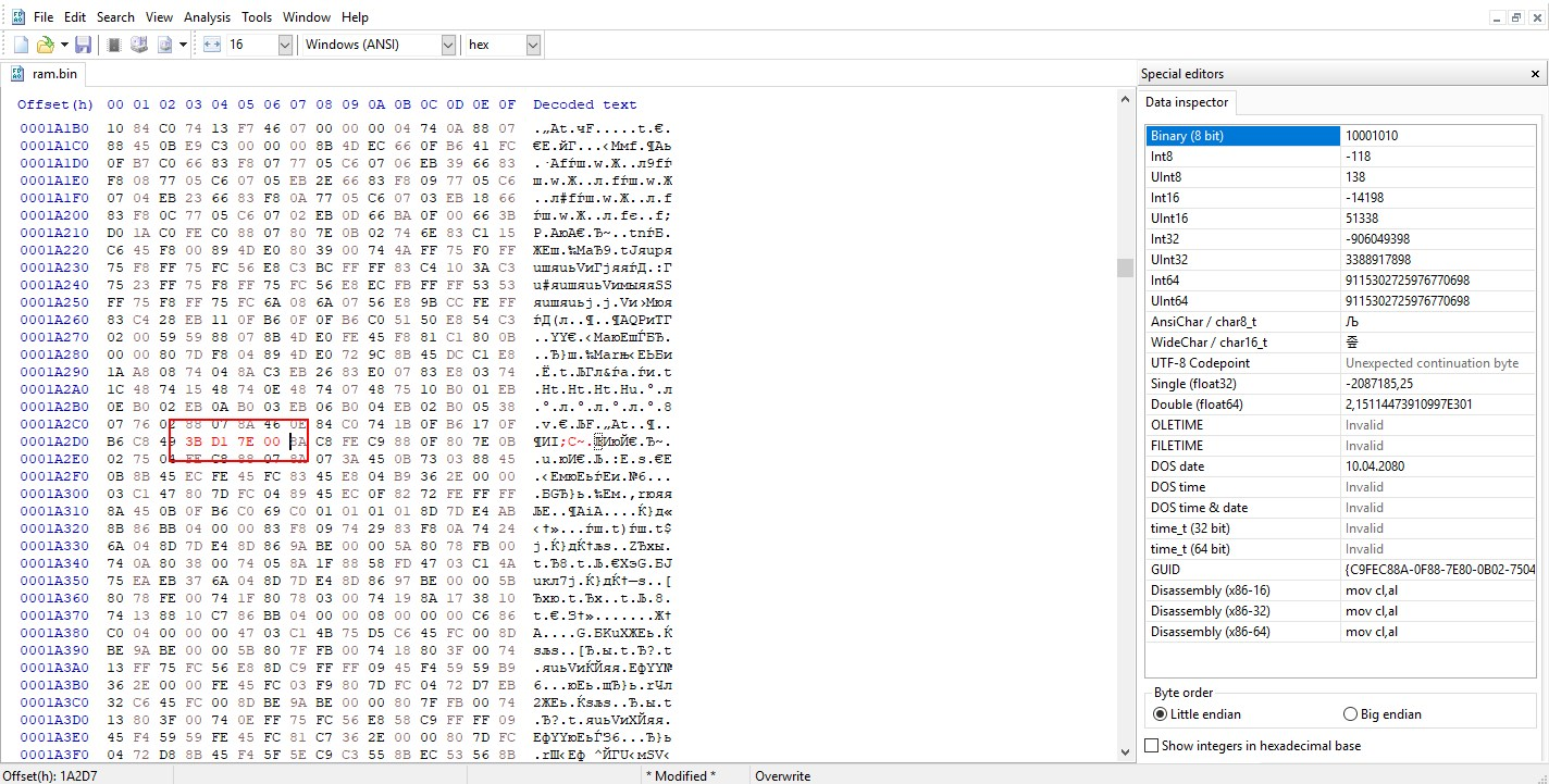
Replace the found bytes with:
3B D1 7E 00
Save the file.
The value replaced and ready to be saved.
Back in UEFITool, right-click the same PE32 image entry and choose Replace body, then select your edited ram file. Replacing the module body with the patched file.
Check the Action column — after this step it should now show Rebuild and Rebase next to the modified entry. That confirms UEFITool registered the change correctly. The RAM overclocking patch is now applied. “Rebuild” and “Rebase” confirm the patch was applied.
If your CPU has a factory-locked multiplier (this applies to the entire Xeon E5-2600/E5-4600 family), you can stop here, save the changes in UEFITool, and skip straight to flashing the modified BIOS — the multiplier unlock in Part 2 won’t do anything useful for you.
Part 2 — Unlocking CPU overclocking (multiplier)
This mod re-enables the “Core Ratio Limit” (multiplier) control for CPUs that support it: the Xeon E5-1600 family (except the Xeon E5-1620 v2) and the Core-i7 family.
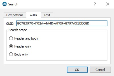
Still in UEFITool, press Ctrl+F again, switch to the GUID tab and search for:
8C783970-F02A-4A4D-AF09-8797A51EEC8D
Searching by GUID — the CPU multiplier module.
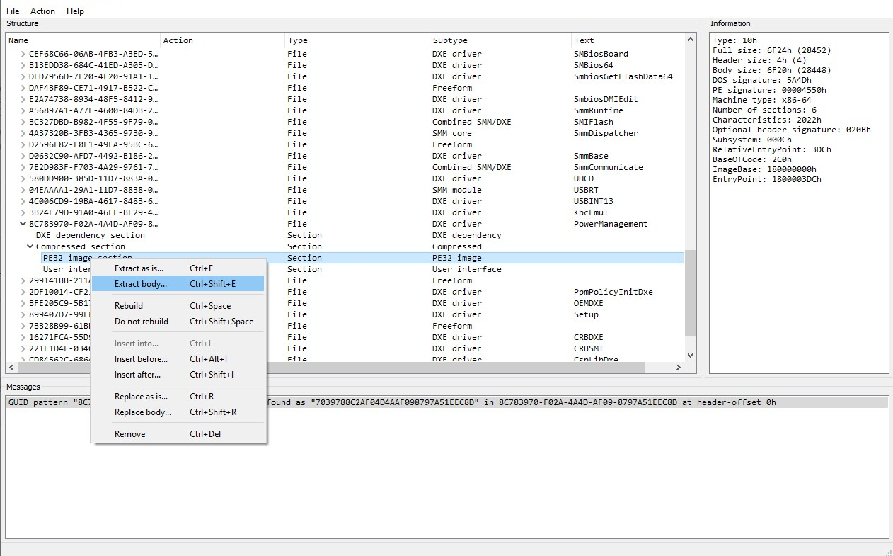
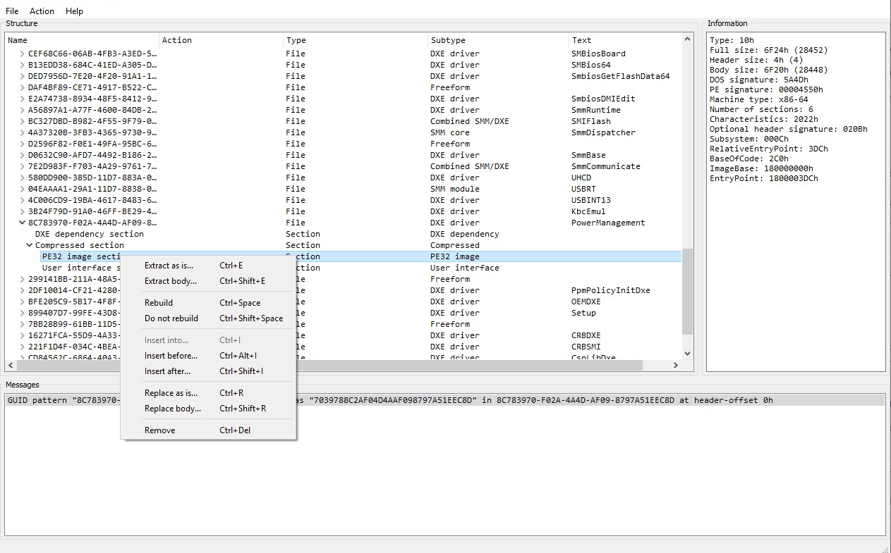
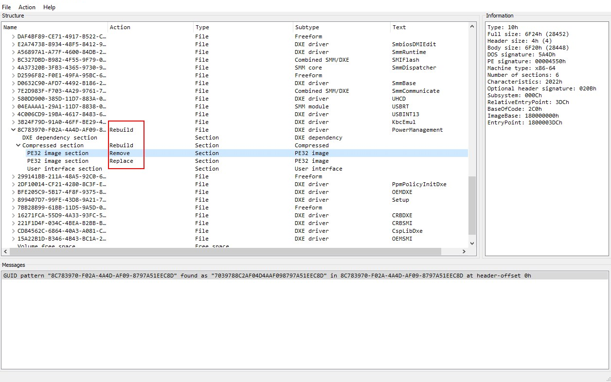
Click OK. Double-click the match at the bottom, then expand the tree. This time you need the PE32 image located inside the PowerManagement module. The PE32 image inside the PowerManagement module.
Right-click it and choose Extract body. Save it with a clear name, such as cpu. Right-click → Extract body.
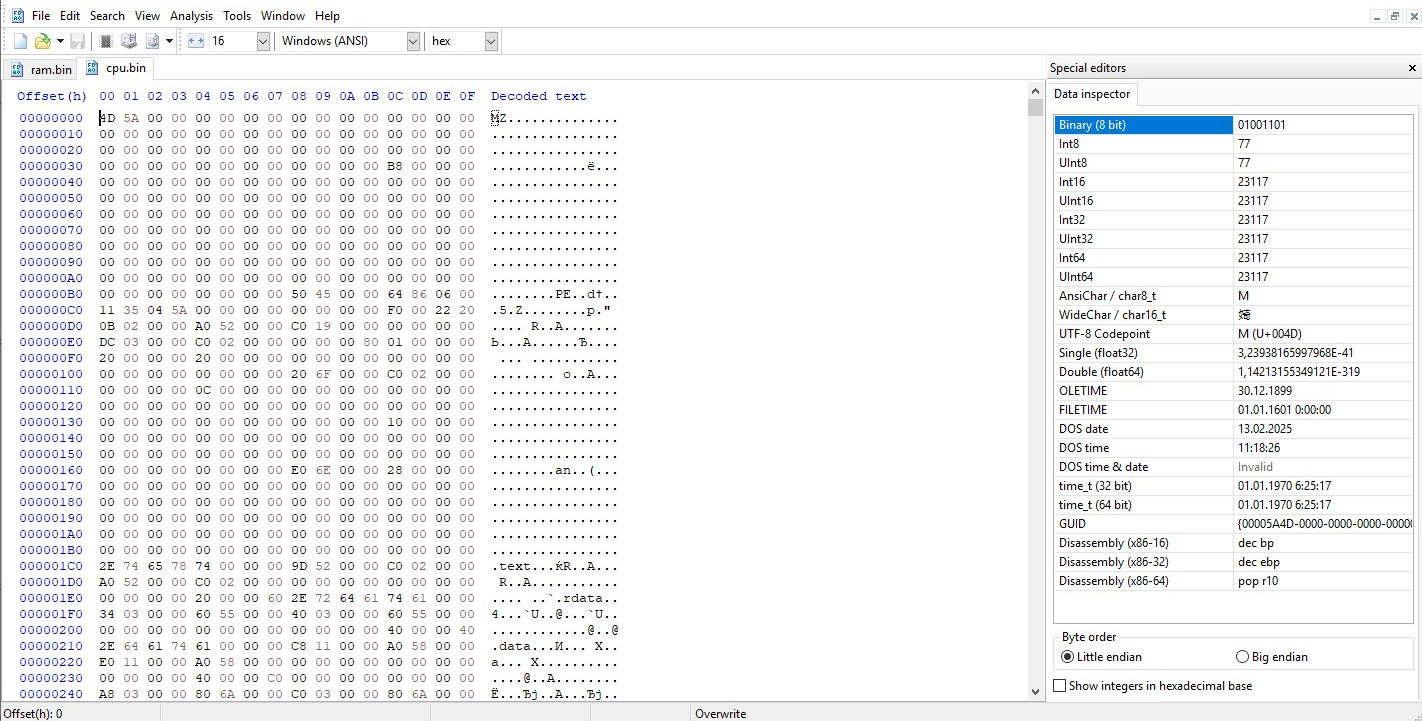
Open the saved cpu file in your hex editor. The extracted module opened in the hex editor.
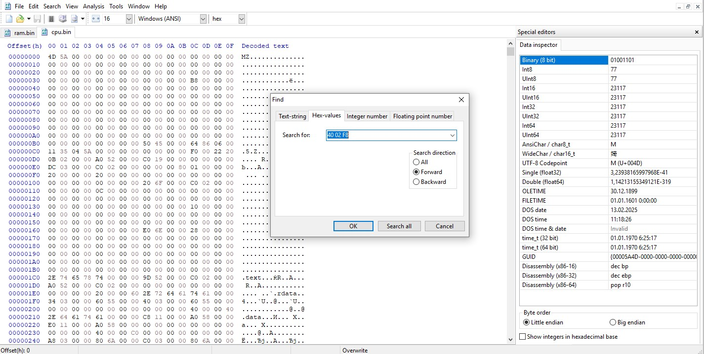
Press Ctrl+F, switch to HEX-values, and search for:
40 02 F8
Searching for the byte pattern that gates the CPU multiplier control.
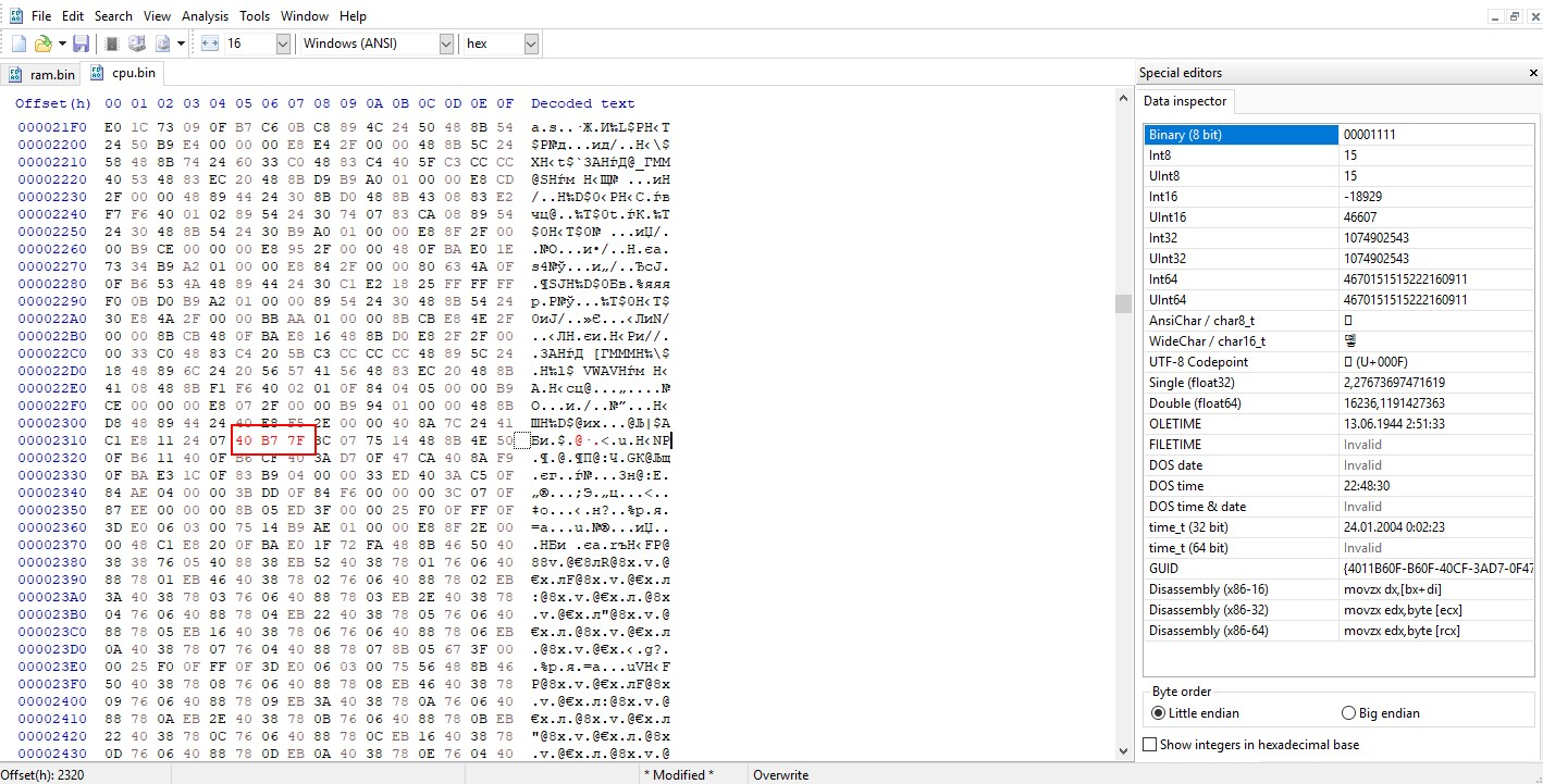
Replace it with:
40 B7 7F
Save the file.
The value replaced and ready to be saved.
Back in UEFITool, right-click the module entry and select Replace body, then choose your patched cpu file. Replacing the module body with the patched file.
Confirm that Rebase and Rebuild now appear in the Action column for this entry. “Rebase” and “Rebuild” confirm the patch was applied.
That’s it. All that remains is to flash your mod BIOS using any method suitable for your board.
Post‑flash checks
Power off completely, clear CMOS (jumper or battery), then power on and enter BIOS.
Load Optimized Defaults, Save & Exit, then re‑enter the BIOS.
Navigate to Advanced → CPU Power Management Configuration and enter the multiplier values for each core. Don’t set maximum values right away — a value around 40 is a reasonably safe starting point to confirm the unlock is working before pushing higher frequencies.
Navigate to Chipset → North Bridge and enter your desired memory frequency in the DDR Speed field.
Save the BIOS settings, boot into the OS, and check if your new values were actually applied using tools like CPU-Z or AIDA64. Once verified, run a stability test to ensure your system is completely stable.
Tips, pitfalls and troubleshooting
Always keep the original dump. Before applying any patch, save an untouched copy of the BIOS you pulled in Step 0, separate from the file you’re editing. It’s your only way to restore the board via software if something goes wrong.
If you can’t find the required values in the hex editor: make sure you’re searching in HEX-values mode specifically. If the original values still can’t be found, search for the replacement (already-patched) values instead — if those turn up, your BIOS already has these patches applied.
If the board won’t boot after flashing (no POST, powers off after a couple of seconds), first try clearing CMOS with the jumper/battery-pull method described above. If that doesn’t help, recovery will require an external SPI programmer.