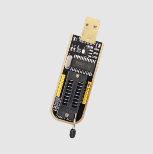
If you’re reading or writing a SPI flash chip with a CH341A-based USB programmer and the read comes back as solid FF, or a write completes but the verification checksum doesn’t match, you’re probably not looking at a dead or miswired chip. It’s a voltage mismatch on the programmer board itself — a well-known hardware flaw on certain cheap CH341A boards, and one with more than one known fix.
It shows up a lot with newer, budget Chinese-market flash chips. Recent Chinese X99 (LGA2011‑3) motherboards are a common place to hit it, since plenty of them switched to this kind of chip in the last few years, but the flaw itself has nothing to do with that platform specifically, or with any one chip brand.
Why it happens
The cheapest CH341A boards share a long-known design shortcut. The CH341A chip itself runs its I/O pins straight off the 5V coming from USB, while a small onboard AMS1117 regulator separately steps that down to 3.3V for the ZIF socket’s VCC pin only, never for the CH341A’s own supply. So a 3.3V-only chip sitting in the socket ends up seeing 5V logic levels on its data lines, out of spec on every board built this way. Most Winbond and Macronix chips shrug this off thanks to margin built into their I/O design, which is why the problem rarely shows up with “ordinary” BIOS chips. Newer, budget Chinese-market flash families like XMC and GallopMem tolerate it noticeably less well, and that’s what produces corrupted reads and failed checksums.
5V on the data lines can permanently damage voltage-sensitive SPI flash chips, not just corrupt a read or write. They’re also more sensitive to poor contact quality and unstable power than traditional Winbond or Macronix parts.
Which CH341A boards are actually affected
There’s no reliable industry-wide version numbering here, so don’t trust the board’s color or a printed version number on its own — verify with a multimeter instead:
- Check it yourself: plug the programmer in (empty ZIF socket is fine) and measure the voltage on pin 28 (VCC) of the CH341A chip, or on the MISO/MOSI data pins at the ZIF socket. Close to 5V, your board has the flaw. Close to 3.3V, it’s already fine.
- The affected type: bare $3–5 “black PCB” ZIF-socket boards with no dedicated level-shifting hardware, just the CH341A chip and a 3.3V regulator feeding only the socket. Some newer production runs of the same board have reportedly started shipping at 3.3V already, but there’s no way to tell from a listing photo, so measure instead of guessing.
- Pricier boards advertising multi-voltage “level conversion” — often sold as “CH341A V1.7,” with a 5V/3.3V/2.5V/1.8V jumper — use a dedicated level-shifter chip and don’t have this problem. Sellers apply the “V1.7” label inconsistently, though, so don’t take it at face value; the multimeter check is what actually tells you.
How it’s fixed
On the affected “black” board, the onboard 3.3V regulator only feeds the ZIF socket. It never touches the CH341A chip’s own supply, which stays at 5V regardless of what’s in the socket. Two fixes are documented for rerouting that supply. Both come from the community, not the manufacturer, so instead of paraphrasing the exact steps here, we’re pointing to the original write-ups:
- Solder fix — the CH341A’s VCC pin gets lifted off the board and rewired directly to the onboard 3.3V regulator’s output, bypassing the 5V feed entirely. It’s the older, more widely documented approach and works regardless of board revision. Full steps with photos: Chuck Nemeth’s write-up, based on the original fix worked out in this EEVblog thread.
- Solderless fix — on boards that already expose a spare 3.3V pin next to a 5V pin on one of the headers, you get the same result by cutting a single trace and bridging two existing pins with a jumper. No soldering iron needed. Full steps with photos: Sawyer Shepherd’s write-up.
Whichever fix you use, check the result with a multimeter before plugging in a chip. Feeding 5V into a 3.3V-only chip is exactly the failure mode you’re trying to avoid.
Sources & further reading
- Step-by-step solder fix, with photos: Chuck Nemeth’s wiki
- Step-by-step solderless fix, with photos: Sawyer Shepherd’s Blog
- The original EEVblog thread this mod comes from: EEVblog forum
- Video demonstration of identifying and fixing the issue: Voltlog #318
- General background and a third documented variant of the fix: OpenIPC wiki

Written by
Senior Hardware Specialist proving you don't need top-tier gear to game. Expert in smart upgrades and budget-friendly PC restoration.